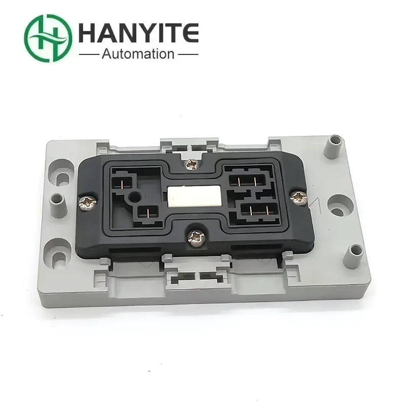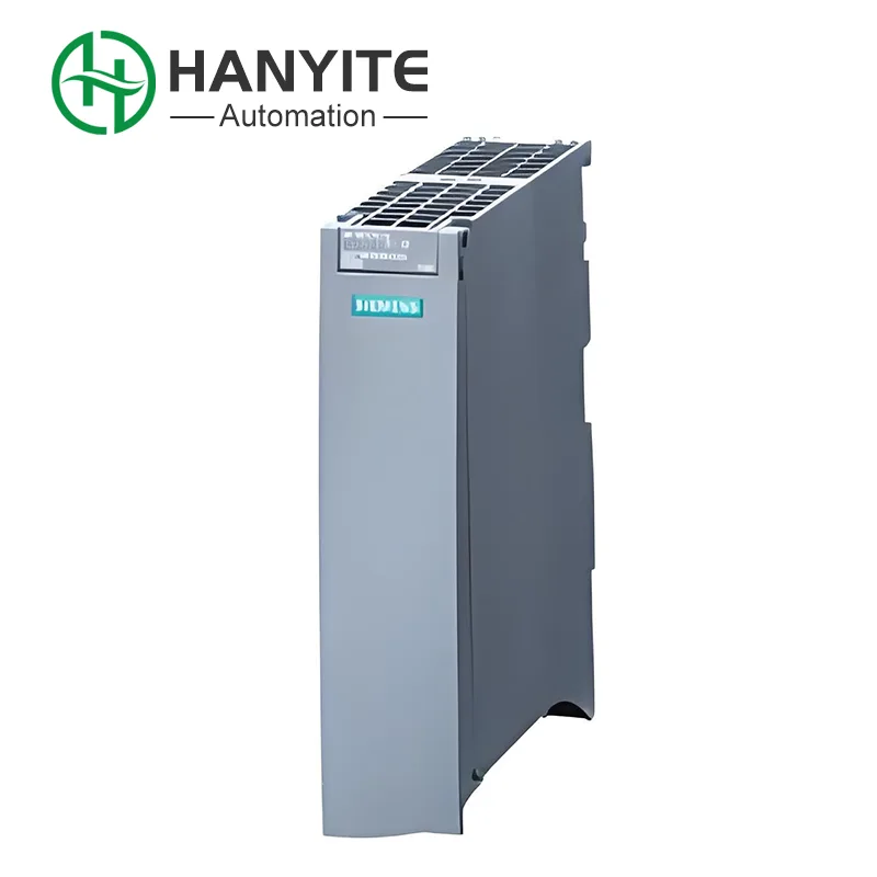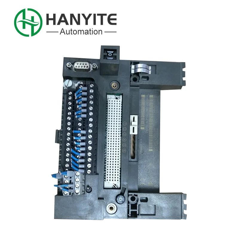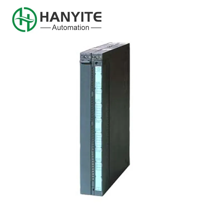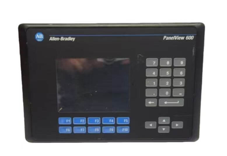



In the renovation of the Kinetix multi-axis servo system, the Allen Bradley 2094-BM02-M is often used to replace the traditional complex parallel hard wiring. Compared with the common problem of old-style discrete terminal connections being susceptible to harmonic interference from the inverter, this bridge module builds a high-speed ring network through an optical fiber interface to achieve nanosecond-level data synchronization. It directly takes power from the backplane bus and eliminates the need for additional power wiring. When the packaging production line needs a batch upgrade, it is connected to the source Factory through Hanyite Automation Technology for bulk procurement. This not only ensures a perfect match between the underlying firmware and the driver of the module, but also effectively prevents refurbished parts from being mixed in, reducing the risk of communication disconnection in multi-axis linkage.
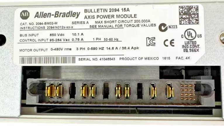
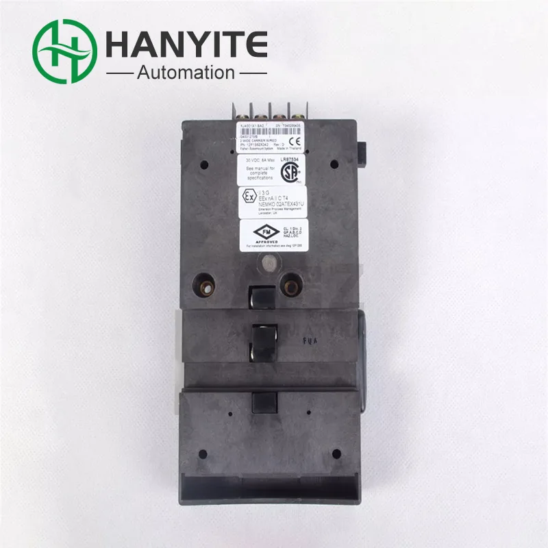
In the Kinetix 6000 multi-axis servo system, the high-speed data synchronization between the axes directly determines the operating accuracy of the equipment. The Allen Bradley 2094-BM02-M acts as the bridge module, mainly undertaking the task of fiber optic loop networking among multiple module drivers. It connects various power segments of the servo units through an internal high-speed bus, ensuring that the data of the position loop and the speed loop is sent to all axes within the same beat. The fiber optic interface at the bottom of the module supports hot swapping, and it can re-establish the communication link even when the system is powered off. This hard-wired synchronization mechanism is much faster than software-level synchronization, and it is particularly suitable for shearing machines or cam cutting equipment that require extremely low follow error.
If the wiring in the servo cabinet is not handled properly, troubleshooting the wiring later can be very painful. Traditional drivers need dozens of shielded wires to connect the enable and alarm signals one-to-one, and the terminal blocks are densely packed. The Allen Bradley 2094-BM02-M transforms the complex parallel wiring into just two fiber optics, saving more than half of the cabinet wiring space. The wiring troughs do not need to be stuffed full. The module panel has clear status indicator lights. A green light that is constantly on indicates that the loop is closed, and a flashing red light directly locates which fiber is broken or not properly plugged. When the on-site electrician replaces a damaged driver unit, they only need to pull out the fiber from the old module and plug it into the new one, without reprogramming or setting node addresses. Power-on is enough to start running.
During the renovation of old production lines, the follow-up errors of servo axes often fluctuated greatly, making the troubleshooting extremely time-consuming. Often, it was only after thorough investigation that it was discovered that the ordinary communication cables of the discrete drivers were interfered with by the harmonics of the frequency converter. After changing to an optical bridge architecture, these intermittent communication soft failures were completely eradicated.
For multi-axis linkage equipment such as stamping or capping machinery, when they are powered on again and homed after an emergency stop, if the response timing of each axis is not synchronized, the mechanical structure is extremely prone to hard interference. By using the bridge module to lock the hardware synchronization clock firmly, all axes can reset at the exact same moment, eliminating the risk of machine collision entirely.
For production lines with long wiring distances in the workshop, analog signal lines are prone to voltage drop, causing the end drivers to frequently report communication failures. By replacing with optical signal wiring, the voltage drop threshold is directly crossed, and along with it, the numerous intermediate relays installed previously for voltage stabilization are eliminated. The number of fault points is significantly reduced.
When the CNC machine executes high-speed G code for circular arcs or corners, the trajectory occasionally deforms. In the end, it is ultimately due to the time difference of a few microseconds between the arrival of the interpolation data packets of each axis. By using the fiber optic ring network at the bottom layer to reduce the delay to the nanosecond level, this extremely subtle data time difference no longer poses a problem.
Q1. How many servo motors can this module directly control?
A: This module itself does not directly connect to the motor power line. Allen Bradley 2094-BM02-M only handles data interaction between the drive units. The actual number of motors it can control depends entirely on how many power modules are mounted in the system. Usually, one logic axis corresponds to one power unit.
Q2. Does high temperature in the cabinet affect the module's operation?
A: The operating environment temperature of the module cannot exceed 60 degrees. If the cabinet has poor heat dissipation and frequently experiences high-temperature disconnections, it is necessary to carefully check if the cabinet top fan is reversed or the filter is clogged. In necessary cases, widen the distance between the driver to improve the air duct.
Q3. Can the connectors on the back of the module be unplugged and plugged in while the equipment is running?
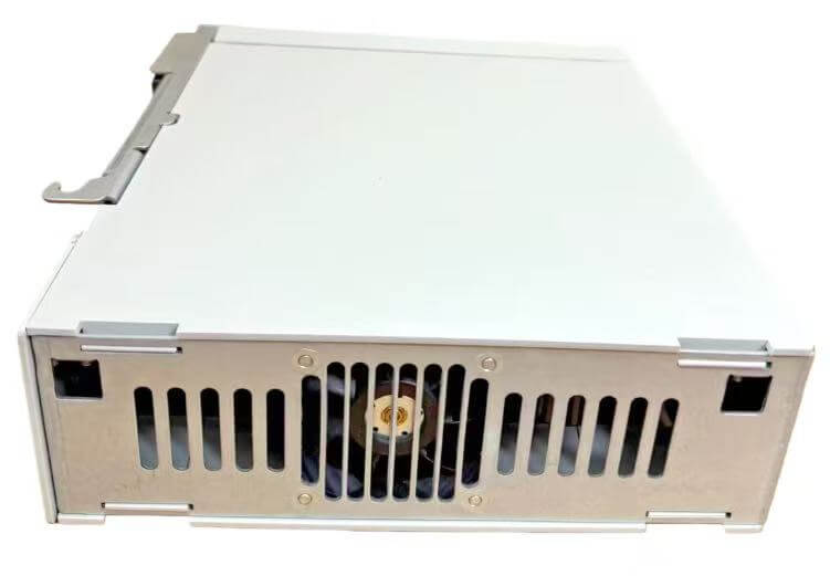
A: Pure optical fiber heads can be unplugged and plugged in without power on. However, it is strictly prohibited to plug or unplug the multi-pin power and communication connector on the back of the module while the servo system is running. Otherwise, it is very likely to generate a surge and burn out the internal bus chip.
Q4. What should I do if the communication is unstable when there are many axes in the system?
A: When the number of axes connected to the system becomes too large, causing the loop load to increase, you can appropriately add bridge modules in the middle of the logical axis for signal relay to prevent intermittent disconnections at the end nodes due to optical signal attenuation.
Address
No. 169, Xinggang 2nd Li, Haicang District, Xiamen, China
Tel